Description
- Brand Name: EMDSXGO
- Accessory Type: Extension Board
- Battery Included: No
- Origin: Mainland China
- High-concerned chemical: None
- Compatible With: new

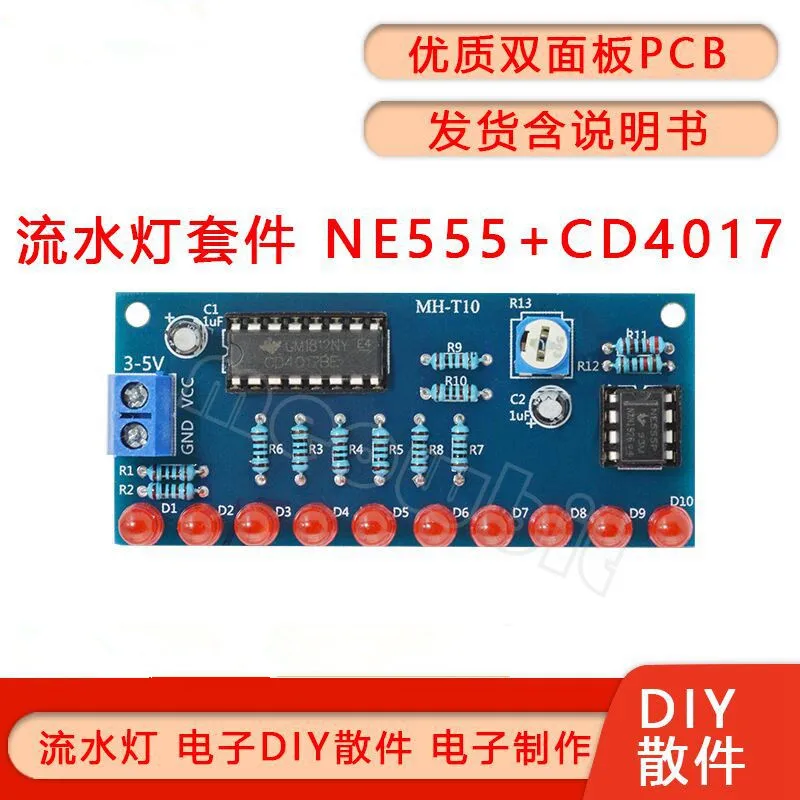
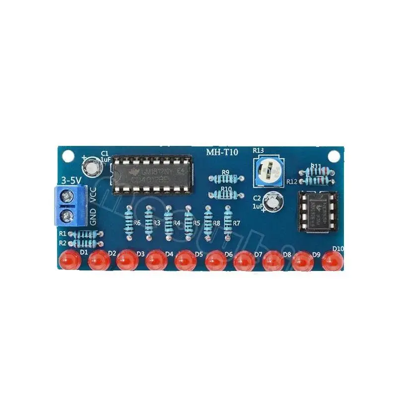
Function introduction: After the power is turned on, 10 LEDs light up in sequence from left to right, showing the state of running water lights. This kit can visually demonstrate the functions of NE555 timing and CD4017 counting, and is a starter kit for learning timers, counters, frequency dividers, and lantern controllers. At the same time, the kit has good effects, is very interesting and practical, and is also the preferred material for beginners to get started
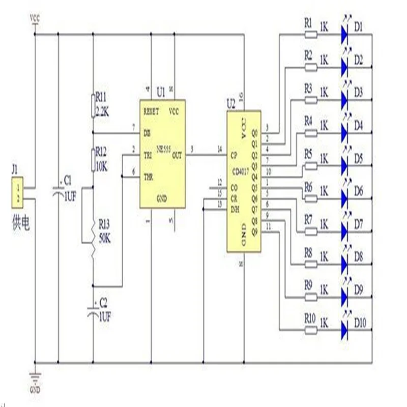
Circuit principle:
This kit is mainly composed of a clock generation circuit and a decimal counter circuit. It is a self-excited multivibrator with NE555 as the core. The power supply charges the capacitor C2 through R11, R12 and R13. When C2 starts to charge, the 2-pin of NE555 is still in the Low level, so pin 3 of the output terminal is high level, when the power supply is charged to C2 to 2/3 of the power supply voltage through R11, R12, R13, the level of pin 3 of the output terminal changes from high to low, and the internal discharge tube of NE555 is turned on , Capacitor C2 is discharged through R13, R12, 7 pins of NE555, until the voltage across C2 is lower than 1/3 of the power supply voltage, the level of 3 pins of NE555 changes from low level to high level. C2 is charged again, This cycle forms oscillations.
The charging time is: 0.695(R11+R12+R13)C2,
The discharge time is: 0.695(R13+R12)C2, adjusting R13 can control the output frequency of the oscillator, the clock oscillation signal of NE555 is continuously added to the 14-pin of CD4017, and 10 LEDs are connected to the 10 output terminals of CD4017, When the 10 output terminals of CD4017 generate high level in turn under the action of the clock signal, D1--D10 will be lit in turn, thus forming the effect of running water lights. Adjusting R13 adjusts the flow rate of the LED light.
Circuit diagram:
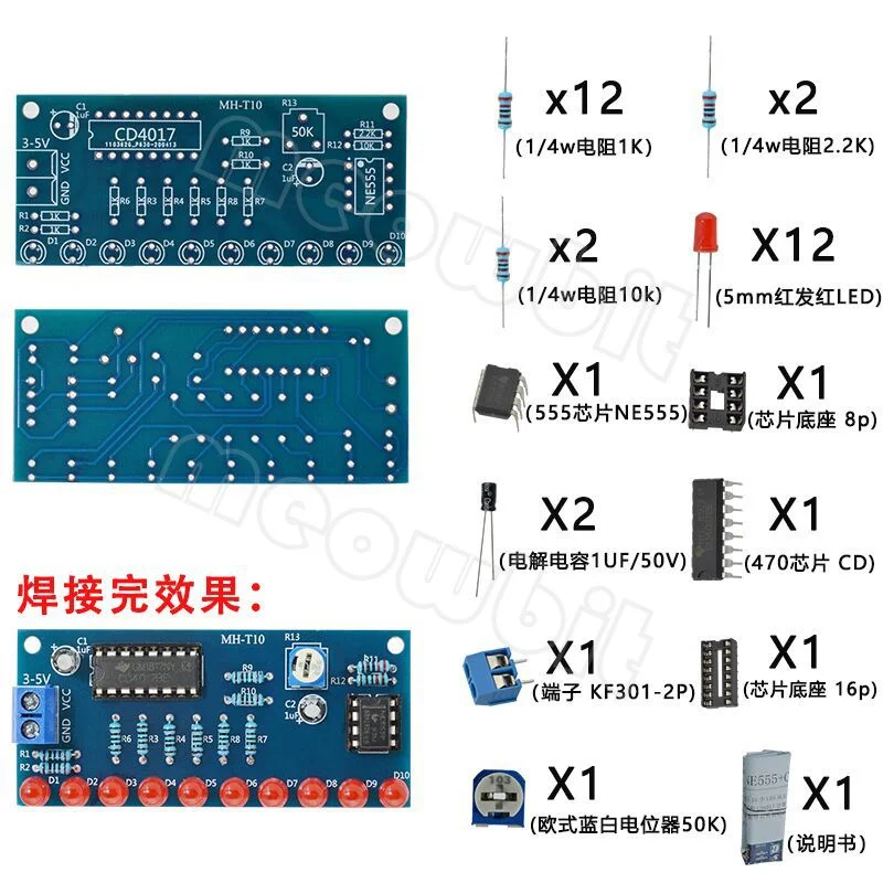
Shipping list:

common problem:
1. Be careful to avoid wrong welding of the positive and negative poles of the LED. The long leg is the positive pole.
2. Be careful to avoid wrong welding of the positive and negative electrodes of the electrolytic capacitor, the long leg is the positive electrode.
3. Be careful to avoid inserting the chip in the opposite direction. The chip notch and the base notch should be in the same direction as the notch on the board.
4. Pay attention to avoid the wrong connection of the positive and negative poles of the power supply. The correct connection method is that VCC is connected to the positive pole, GND is connected to the negative pole, and the power supply is 3-5V DC voltage.
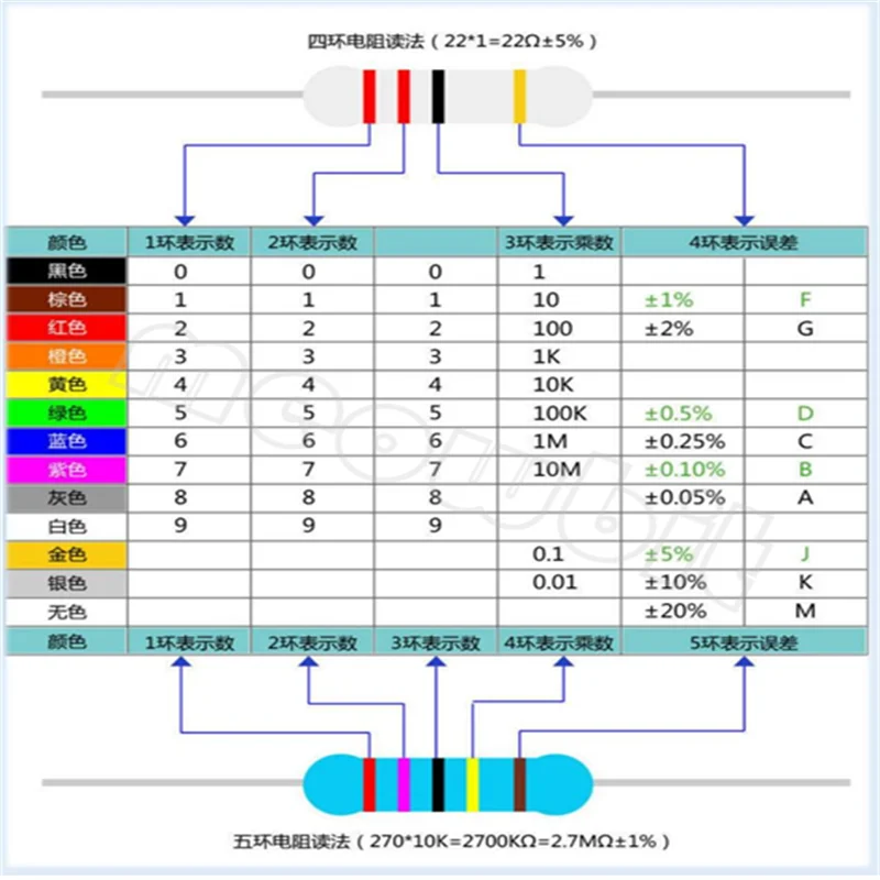
Pay attention to check whether there are short circuits and virtual soldering in the welding. Appendix: The specific identification method of four-ring and five-ring color ring resistance